
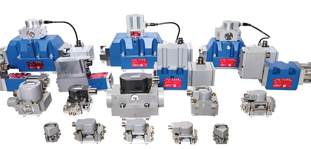
Proportional servo valves are advanced hydraulic control components that integrate the proportional control feature of proportional valves and the high-precision dynamic response capability of servo valves. Their core function is to convert electrical signals (voltage/current) into hydraulic signals (flow/pressure) proportionally and with high accuracy, thereby achieving precise closed-loop control over the position, speed, force, and other parameters of hydraulic actuators (such as cylinders and motors). To understand their working mechanism thoroughly, it is necessary to analyze their structural composition, signal conversion logic, and core control mechanism.
1. Core Structural Composition
The structure of proportional servo valves is designed to ensure accurate signal transmission and low-loss hydraulic control. It mainly consists of four interrelated modules, each playing a crucial role in the "electrical-mechanical-hydraulic" signal chain:
| Module Name | Core Components | Core Function |
|---|---|---|
| Electrical Input Module | Proportional solenoid (or torque motor) | Converts external electrical signals (e.g., 0-10V voltage, 4-20mA current) into electromagnetic force or torque. |
| Mechanical Amplification Module | Force feedback lever, nozzle-flapper mechanism (or spool) | Amplifies the electromagnetic force or torque to drive the movement of hydraulic control components. |
| Hydraulic Control Module | Main spool (spool structure with precision orifices) | Controls the on-off of hydraulic oil and adjusts the flow rate or pressure by the displacement of the spool. |
| Feedback and Correction Module | Displacement sensor (e.g., LVDT - Linear Variable Differential Transformer) | Real-time detection of the main spool displacement, feedback of the signal to the controller, and formation of closed-loop correction. |
2. Core Working Logic: From Signal Input to Closed-Loop Control
The working process of proportional servo valves follows a cyclic "electrical signal → mechanical action → hydraulic output → feedback correction" logic, which ensures high-precision control. The specific steps are as follows:
Step 1: Electrical Signal Input
The external control system (such as a PLC, motion controller, or industrial computer) sends a target electrical signal according to the control requirements (e.g., adjusting the extension speed of a cylinder). This signal is usually a standard analog signal (0-10V or 4-20mA), where the magnitude of the signal corresponds to the target hydraulic output (e.g., a higher current means a larger required flow rate).
Step 2: Electrical-Mechanical Conversion
The proportional solenoid (or torque motor) in the electrical input module receives the electrical signal and converts it into a proportional electromagnetic force or torque. For example, a proportional solenoid generates a larger electromagnetic force when the input current increases; a torque motor generates a rotational torque that drives the mechanical structure to deflect.
Step 3: Mechanical Amplification
The electromagnetic force or torque generated in the previous step is relatively small and cannot directly drive the main spool (which requires larger driving force to overcome hydraulic resistance). The mechanical amplification module (e.g., nozzle-flapper mechanism) amplifies this force or torque. Taking the nozzle-flapper mechanism as an example: the torque from the torque motor drives the flapper to deflect, changing the gap between the flapper and the two nozzles. This gap change leads to a pressure difference in the control chamber, which pushes the main spool to move.
Step 4: Hydraulic Output Control
The displacement of the main spool directly determines the opening size and direction of the precision orifices in the hydraulic control module. When the spool moves, it adjusts the flow path and flow rate of the hydraulic oil:
- Flow Control: A larger spool displacement increases the orifice opening, allowing more hydraulic oil to flow into the actuator (e.g., cylinder), increasing its movement speed.
- Pressure Control: By adjusting the orifice opening, the pressure loss of the hydraulic oil is changed, thereby controlling the output pressure to the actuator (e.g., adjusting the clamping force of a hydraulic clamp).
Step 5: Closed-Loop Feedback and Correction
The displacement sensor (e.g., LVDT) in the feedback module real-time monitors the actual displacement of the main spool and converts this mechanical displacement into an electrical feedback signal. This feedback signal is sent back to the external controller, which compares it with the initial target signal. If there is a deviation (e.g., the actual spool displacement is smaller than the target displacement due to hydraulic load changes), the controller adjusts the input electrical signal in real time. This adjustment changes the electromagnetic force/torque, corrects the spool displacement, and ensures that the hydraulic output (flow/pressure) accurately matches the target requirement.
3. Key Advantages Supporting High-Precision Control
The working principle of proportional servo valves gives them three core advantages that make them suitable for high-demand hydraulic control scenarios:
- Proportionality: The hydraulic output (flow/pressure) has a linear proportional relationship with the input electrical signal, ensuring predictable and controllable control effects.
- High Dynamic Response: The combination of the torque motor (or high-performance proportional solenoid) and the feedback mechanism enables the valve to quickly respond to changes in the input signal (response time usually in milliseconds), adapting to rapid changes in load or control requirements.
- Closed-Loop Stability: The real-time feedback and correction mechanism eliminates errors caused by factors such as hydraulic oil viscosity changes, load fluctuations, and mechanical wear, maintaining long-term control stability.
4. Typical Application Scenarios
Due to their high precision and stability, proportional servo valves are widely used in fields requiring precise hydraulic control, such as:
- Industrial automation: Precision positioning of CNC machine tools, injection molding machines, and robotic arms.
- Construction machinery: Stable control of excavator boom speed and pressure, and concrete pump displacement adjustment.
- Aerospace and defense: Attitude control of aircraft landing gear and hydraulic servo systems of missile launchers.